
Error Code Lookup
Find the meaning and solution for error codes displayed on your Mitsubishi Electric products.
Select Product Category

Enter Error Information
Search Error Code
Error Code Results (31 results)
| # | Error Code | Primary error code | Primary error detail code | Searched device | Description / Cause | Solution | Remark |
|---|---|---|---|---|---|---|---|
| 1 | 0404 | - | - | Indoor |
Abnormal if data cannot be read normally from the nonvolatile memory of the indoor controller board. Defective indoor controller board. |
Replace indoor controller board. View details |
- |
| 2 | 0900 | - | - | Lossnay |
เดินเครื่องทดสอบ |
- View details |
- |
| 3 | 1301 | - | - | Outdoor |
Low pressure fault. 1.Inner pressure drop due to a leakage. |
1.Pressure 0 ~ 1.7 MPa [247psi]. 2.Vout 0.5 ~ 3.5 V (0.173 V / 0.098 MPa [14 psi]) View details |
- |
| 4 | 1302 | 1402 | - | Outdoor |
High pressure fault 1 (Outdoor unit) 1.Outdoor unit LEV2 actuation failure -> Cooling. |
1.Check resistance : 0.25W 1kΩ LED : DC15V 20mA or more. 2.Confirm that the refrigerant service valve is fully open. 3-4.Check the outdoor units for problems and correct them,If any. 5.Check the fan on the outdoor unit.(252). 6.In case of SV1a (Bypass valve) This solenoid valve opens when powered (Relay ON). 6.1) At compressor start-up, the SV1a turns on for 4 minutes, and the operation can be checked by the self-diagnosis LED displayand the closing sound. 6.2) To check whether the valve is open or closed, check the change of the SV1a downstream piping temperature while the valve is being powered.Even when the valve is closed, high-temperature refrigerant flows inside the capillary next to the valve. (Therefore, temperature of the downstream piping will not be low with the valve closed.). 7.Check thermistor resistance. (TH3, TH7). 7.1) TH3. Short detection:. 110°C [230°F] and above (0.4 kΩ). Open detection:. -40°C [-40°F] and below (130 kΩ). 7.2) TH7. Short detection:. 110°C [230°F] and above (0.4 kΩ). Open detection:. -40°C [-40°F] and below (130 kΩ). 8.The high pressure sensor consists of the circuit shown in the figure below. If DC 5V is applied between the red and the black wires, voltage corresponding to the pressure between the white and the black wires will be output, and the value of this. voltagewill be converted by the microcomputer. The output voltage is 0.071V per 0.098MPa [14psi]. 9.Check the temperature and the pressure of the sensor with LED monitor. 10-11.Check the temperature and the pressure of the sensor with LED monitor. 12.Check the input voltage at the power supply terminal block (TB1). View details |
- |
| 5 | 1500 | 1600 | - | Outdoor |
Refrigerant overcharge 1.Overcharged refrigerant. |
1.Evaluating and Adjusting Refrigerant Charge. 2.Check the temperature and pressure readings on the sensor that are displayed on the LED monitor. 3.Check the temperature and pressure readings on the thermistor that are displayed on the LED monitor. 4.The valve opening changes according to the number of pulses. 4.1) Connections between the outdoor control board and LEV1. (outdoor expansion valve). 4.2) Pulse signal output and valve operation. 4.3) LEV valve closing and opening operation. 5. Malfunction:. Refer to the Service Handbook of the indoor unit. LEV leakage:. Check the LEV on the stopped indoor unit in the cooling mode for refrigerant leak. 6.Check that the twinning-pipe kit is installed in accordance with the instructions provided in the installation manual. View details |
- |
| 6 | - | 1605 | - | Outdoor |
Preliminary suction pressure fault. |
- View details |
- |
| 7 | 2500 | - | - | Indoor |
Drain pump fault.(Models with a drain sensor) 1. Drain pump failure. |
1. Check for proper functioning of the drain pump. 2. Check for proper drainage. 3. 1) Check for proper lead wire installation. 2) Check for clogged filter. 4. If the above item checks out OK, replace the indoor unit control board. 5. Check the solenoid valves on the indoor unit for leaks. View details |
- |
| 8 | 2500 | - | - | Indoor |
Drain sensor submergence. 1. Drain water drainage problem. |
1. Check for proper drainage. 2. Check for proper lead wire installation. Check for clogged filter. 3. Replace the relay. 4. If the above item checks out OK, replace the indoor unit control board. View details |
- |
| 9 | 2502 | - | - | Indoor |
ปั๊มนํ้าทิ้งขัดข้อง (รุ่นที่มีสวิตช์ลูกลอย) 1. ปั๊มนํ้าทิ้งขัดข้อง |
1. ตรวจสอบว่ากลไกปั๊มนํ้าทิ้งทำงานได้อย่างถูกต้อง. 2. ตรวจสอบว่าระบายน้ำได้ดีหรือไม่. 3. ตรวจสอบว่าสวิตช์ลูกลอยทำงานปกติ. 4. ตรวจสอบความต้านทานเมื่อเปิดและปิดสวิตช์ลูกลอย. 5. เปลี่ยนแผงวงจรควบคุมเครื่องภายในอาคาร. 6. ตรวจสอบวาล์วโซลินอยด์บนเครื่องภายในอาคารสำหรับรอยรั่ว View details |
- |
| 10 | 2503 | - | - | Indoor, Lossnay |
Drain sensor (Thd) fault. 1. Faulty connector (CN31) insertion. |
1. Check for connector connection failure. Reinsert the connector, restart the operation, and check for proper operation. 2. Check for a broken thermistor wire. 3. Check the resistance of the thermistor. 0°C[32 °F]:6.0 kΩ. 10°C[50 °F]:3.9 kΩ. 20°C[68°F]:2.6 kΩ. 30°C[86°F]:1.8 kΩ. 40°C[104 °F]:1.3 kΩ. 4. Replace the indoor unit control board if the problem recurs when the unit is operated with the No.-1 and No.-2 pins on the drain sensor connector (CN31) being short-circuited. If the above item checks out OK, there are no problems with the drain sensor. Turn off the power and turn it back on. View details |
- |
| 11 | 2600 | - | - | Lossnay |
Water leakage. |
Check that water does not leak from the pipes in such as the humidifier. View details |
- |
| 12 | 2601 | - | - | Lossnay |
Water supply cutoff. 1. The water tank of the humidifier is empty. |
1. 1) Check the amount of supply water. 2) Check for the solenoid valve and for the connection. 2. Check the connector. 3. Check the connecting part. 4. Check for the float switch. 5. Turn off the power source of the water tank to defrost, and turn it on again. View details |
- |
| 13 | 4102 | 4152 | - | Outdoor |
Open phase. 1. Power supply problem. |
1. Check the input voltage to the power supply terminal block TB1. 2. 2.1) Check the coil connections. 2.2) Check for coil burnout. 2.3) Confirm that the voltage at the CN3 connector is 198 V or above. 3. Confirm that the voltage at the control board connector CNAC is 198 V or above. (If the voltage is below 198V, check the wiring connection between the noise filter board CN3, noise filter board CN2 and control board CNAC. Confirm that the wiring between noise filter TB23 and INV board SC-L3 is put through CT3.). 4. Check for a blown fuse (F01) on the control board. (If a blown fuse is found, check for a short-circuiting or earth fault of the actuator.). 5. Replace the inverter if this problem is detected after the compressor has gone into operation. 6. Replace the control board if none of the above is causing the problem. View details |
- |
| 14 | 4106 | - | - | Outdoor |
Transmission power output failure. 1. Wiring failure. |
Check the transmission power supply circuit on all outdoor units in a given refrigerant circuit for problems. View details |
- |
| 15 | 4109 | - | - | Indoor |
Indoor unit fan operation error. 1. Auxiliary relay (X13) fault. |
1. The coil or the wiring of the auxiliary relay connected to CN28 is faulty. 2. Check the connector for proper connection. 3. Check the fuse on the control circuit board. 4. Check the unit fan for proper operation in the test run mode. If no problems are found with items 1 through 3 above and the fan does not operate,. replace the motor. View details |
- |
| 16 | 4115 | - | - | Outdoor |
Power supply signal sync error. 1. Power supply error. |
1. Check the voltage of the power supply terminal block (TB1). 2. Check the coil connections. 2.1) Check for coil burnout. 2.2) Confirm that the voltage at the CN3 connector is 198 V or above. 3. Check fuse F01 on the control board. 4. Confirm that the voltage at the control board connector CNAC is 198 V or above. 5. If none of the items described above is applicable, and if the trouble reappears even after. the power is switched on again, replace the control board. View details |
- |
| 17 | 4116 | - | - | Indoor, Lossnay |
RPM error/Motor error. 1. Board failure. |
1. Replace the board. 2. Check for the motor and the solenoid switch. View details |
- |
| 18 | 4121 | 4171 | - | Outdoor |
Function setting error. 1. Dip switch setting error on the control board. |
1. Check the SW6-1 setting on the control board. 2. Check that nothing is connected to the connector CNAF on the control board. 3. Replace the control board if no problems are found with the two items above. View details |
- |
| 19 | 4124 | - | - | Indoor |
Electric system not operate due to damper abnormality. The damper is not located at the designated position. |
1) Check there is something that interferes the opening or closing movement of the damper. 2) If damper does not open or close, turn OFF the power supply and measure the resistance of. the damper lock motors (ML1,ML2) and the damper motor (MV2). The resistance value is normal each. →Replace the indoor electronic control P.C. board. The resistance value is not normal each. →Replace the motor that indicates the abnormal value. 3) If damper opens or closes, measure the voltage between CN1X1 (+) and (-) and the voltage. between CN1Y1 (+) and (-) during the damper open by pressing VANE CONTROL button. There is not 0V DC between CN1X1 (+) and (-). →Replace the damper limit switch (open). There is not 5V DC between CN1X1 (+) and (-). →Replace the damper limit switch (close). 4) If damper opens or closes and voltages in 3) are normal, measure the voltage between CN1X1 (+) and (-) and the voltage between CN1Y1 (+) and (-) during the damper close by pressing VANE CONTROL button. There is not 5V DC between CN1X1 (+) and (-). →Replace the damper limit switch (open). There is not 0V DC between CN1X1 (+) and (-). →Replace the damper limit switch (close). There is 5V DC between CN1X1 (+) and (-) and 0V DC between CN1X1 (+) and (-). →Replace. the indoor electronic control. P.C. board. View details |
- |
| 20 | 4220 | 4320 | 0 | Outdoor |
Backup operation. (0) |
- View details |
- |
| 21 | 4220 | 4320 | 108 | Outdoor |
Abnormal bus voltage drop (Detail code 108). If Vdc 289V or less is detected during Inverter operation. (S/W detection) |
1. Power supply environment. Find out if there was a (momentary) power failure. Check whether the power voltage (Between L1 and L2, L2 and L3, and L1 and L3) is 342V. or less across all phases. 2. Voltage drop detected. 4220. 2.1) Check the voltage between the FT-P and FT-N terminals on the INV board while the inverter is stopped and if it is 420 V or above, check the following items. 2.1.1) Confirm on the LED monitor that the bus voltage is above 289V. Replace the INV board if it is below 289 V. 2.1.2) Check the voltage at CN72 on the control board. →Go to (3). 2.1.3) Check the noise filter coil connections and for coil burnout. 2.1.4) Check the wiring connections between the following sections Between the noise filter board and INV board. Between the INV board and DCL.Replace 72C if no problems. are found. 2.1.5) Check the IGBT module resistance on the INV board. 2.2 Check the voltage between the FT-P and FT-N terminals on the INV board while the inverter is stopped and if it is less than 420 V, check the following items. 2.2.1) Check the coil connections and for coil burnout on the noise filter. 2.2.2) Check the wiring between the noise filter board and INV board. 2.2.3) Check the connection to SCP1 and SC-P2 on the INV board. 2.2.4) Check the in-rush current resistor value. 2.2.5) Check the 72C resistance value. 2.2.6) Check the DCL resistance value. Replace the INV board if no problems are found. 3. แผงวงจรควบคุมผิดปกติ. ตรวจสอบว่าได้จ่ายแรงดันไฟฟ้า 12VDC ไปที่ขั้วต่อ CN72 บนแผงวงจรควบคุม ขณะอินเวอร์เตอร์ทำงาน หากไม่ได้จ่ายแรงดันไฟฟ้าหรือค่าไม่ถูกต้อง ให้ตรวจสอบฟิวส์ F01 หากไม่พบความผิดปกติเกี่ยวกับฟิวส์ ให้เปลี่ยนแผงวงจรควบคุม View details |
- |
| 22 | 4220 | 4320 | 109 | Outdoor |
Abnormal bus voltage rise (Detail code 109). If Vdc ≥ 830V is detected during inverter operation. |
1. Different voltage connection. Check the power supply voltage on the power supply terminal block (TB1). 2. INV board failure. 2.1) If the problem recurs, replace the INV board or fan board. In the case of 4220: INV board. In the case of 4225: Fan board. In the case of 4226: Fan board. (Fan box side) View details |
- |
| 23 | 4220 | 4320 | 111 | Outdoor |
Logic error (Detail code 111, 112) 1. In the case of 4220 |
H/W error logic circuit operates, and no identifiable error is detected. View details |
- |
| 24 | 4220 | 4320 | 131 | Outdoor |
Low bus voltage at startup. (Detail code 131) When Vdc 160 V is detected just before the inverter operation. |
Same as detail code 108 of 4220 error. View details |
- |
| 25 | 4230 | 4330 | - | Outdoor |
Heatsink overheat protection. (Detail Code 125) the heat sink temperature (THHS) remains at or above 105°C [221°F] is detected. |
1. Fan board failure. 1.1) Checking the Fan Board Error Detection Circuit at No Load. 1.2) Checking the Fan Inverter for Damage at No Load. 1.3) Checking the Fan Inverter for Damage with Load. 2. Outdoor unit fan failure. 2.1) Check the outdoor unit fan operation. If any problem is found with the fan operation. 2.2) Cecking the Fan Motor for Ground Fault and Coil Resistance Problems. 3. Check that the heat sink cooling air passage is not blocked. 4. Check for proper installation of the INV board IGBT. (Check for proper installation of the IGBT heatsink.). Check the THHS sensor reading on the LED monitor. →If an abnormal value appears, replace the INV board. View details |
- |
| 26 | 4240 | 4340 | - | Outdoor |
Overload protection. If the output current of "(Iac) >Imax (Arms)" or "THHS > 100°C [212°F] " is continuously detected for 10 minutes or more during inverter operation. |
1. Air passage blockage. Check that the heat sink cooling air passage is not blocked. 2. Power supply environment. Power supply voltage is 342 V or above. 3. Inverter failure,. 4. Compressor failure,. Check that the compressor has not overheated during operation. → Check the refrigerant circuit (oil return section). 5. The model selection switches (SW5-3 - 5-8) on the outdoor unit are set incorrectly. Check the setting for the model selection switch on the outdoor unit (Dipswitches SW5-3 - 5-8 on the outdoor unit control board). View details |
- |
| 27 | 4250 | 4350 | 0 | Outdoor |
การทำงานสำรอง(รหัสรายละเอียด 0) |
- View details |
- |
| 28 | 4225 | 4325 | 0 | Outdoor |
Backup operation. (0) |
- View details |
- |
| 29 | 4225 | 4325 | 108 | Outdoor |
แรงดันไฟบัสตกลงผิดปกติ(รหัสรายละเอียด 108) หากตรวจพบว่าแรงดันไฟฟ้า Vdc อยู่ที่ 289V หรือตํ่ากว่าระหว่างการทำงานของอินเวอร์เตอร์ (การตรวจจับซอฟต์แวร์) |
1. สภาพแวดล้อมแหล่งจ่ายไฟ. ตรวจสอบว่าแหล่งจ่ายไฟผิดปกติ (ชั่วคราว) หรือไม่. ตรวจสอบว่าแรงดันไฟฟ้า (ระหว่าง L1 กับ L2, L2 กับ L3 และ L1 กับ L3) อยู่ที่ 342V หรือตํ่ากว่าทุกเฟส. 2. ตรวจสอบแรงดันไฟฟ้าตก. ตรวจสอบแรงดันไฟฟ้าที่ CNVDC บนแผงวงจรพัดลม ขณะอินเวอร์เตอร์ไม่ทำงาน หากอยู่ที่ 420V หรือสูงกว่า ให้ตรวจสอบข้อต่อไปนี้. 2.1) ตรวจสอบแรงดันไฟฟ้าที่ CN72 บนแผงวงจรควบคุม → ไปที่ 3). 2.2) ตรวจสอบการเชื่อมต่อคอยล์ชุดกรองสัญญาณรบกวนและสภาพคอยล์ (รอยไหม้). 2.3) ตรวจสอบการเดินสายไฟระหว่างส่วนต่างๆ ต่อไปนี้. ระหว่างแผงวงจร INV แผงวงจรชุดกรองสัญญาณรบกวน กับแผงวงจรพัดลม. 2.4) ตรวจสอบรายละเอียดของ 4220. เปลี่ยนแผงวงจรพัดลม หากไม่พบความผิดปกติ. ตรวจสอบแรงดันไฟฟ้าที่ CNVDC บนแผงวงจรพัดลม ขณะอินเวอร์เตอร์ไม่ทำงานหากตํ่ากว่า 420V ให้ตรวจสอบข้อต่อไปนี้. 2.4.1) ตรวจสอบสถานะการเดินสายไฟระหว่างแผงวงจร INV กับแผงวงจรพัดลม. 2.4.2) ตรวจสอบรายละเอียดของ 4220. เปลี่ยนแผงวงจรพัดลม หากไม่พบความผิดปกติ. 3. แผงวงจรควบคุมผิดปกติ. ตรวจสอบว่าได้จ่ายแรงดันไฟฟ้า 12VDC ไปที่ขั้วต่อ CN72 บนแผงวงจรควบคุม ขณะอินเวอร์เตอร์ทำงาน หากไม่ได้จ่ายแรงดันไฟฟ้าหรือค่าไม่ถูกต้อง ให้ตรวจสอบฟิวส์ F01 หากไม่พบความผิดปกติเกี่ยวกับฟิวส์ ให้เปลี่ยนแผงวงจรควบคุม View details |
- |
| 30 | 0403 | 4300, 4305, 4306 | 1, 5, 6 | Indoor, Outdoor |
Serial communication error/Panel communication error (1) Incorrect switch setting on the indoor unit circuit |
(1) Check SW3-3 on the indoor unit circuit board Set SW3-3 to ON only when connecting an auto filter cleaning unit. (2) Check the LED1 (cleaning unit circuit board (microcomputer power)). Lit: Power is supplied properly. Unlit: Check for loose or. disconnected power wire between the indoor unit circuit board (CNAC) and the cleaning unit circuit board (CN3A). (3,4,5,6) Check the LED4 (cleaning unit circuit board (communication)). Blinking: Normal communication Unlit: Check for loose or disconnected. communication wire between the indoor unit circuit board (CN3G) and the cleaning unit circuit board (CN3G). If the LED blinks at irregular intervals (normally blinks at 0.5-second intervals), electrical interference is suspected. Check the items above,. turn the power off, and turn the power back on. If the error persists, replace either the cleaning unit circuit board or the indoor unit circuit board. View details |
- |
| 31 | 1102 | 1202 | - | Outdoor |
Discharge temperature fault (1) Gas leak, gas shortage |
(1) Evaluating and Adjusting Refrigerant Charge. (2) Check operating conditions and operation status of indoor/. outdoor units. (3), (4) Perform a cooling operation to check the operation. Cooling: Indoor unit LEV, LEV1, LEV2. Refer to the following page(s). Troubleshooting LEV Problems. (5) Confirm that the refrigerant service valve is fully open. (6) Check the fan on the outdoor unit. Troubleshooting Outdoor Unit Fan Problems. (7) Perform a cooling operation and check the operation. (8) Error Codes [5102, 5103, 5104, 5106, 5107]. (9) Check the inlet air temperature on the LED monitor. View details |
- |
No matching error found
Try adjusting your search terms.
How to check error by yourself
Self-diagnosis guide for Mitsubishi Electric products
Checking via Wireless Remote Control
The City Multi VRF system supports error code retrieval using the standard wireless remote control. Follow these steps to read the error code displayed on the remote:
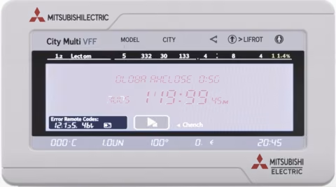
Step-by-step guide
- Point the wireless remote control at the indoor unit.
- Press and hold the CHECK button for 3 seconds until the display changes.
- The remote display will show the current error code (e.g., 6607, 6831).
- Note the 4-digit error code shown on the remote display.
- Press the CHECK button again to cycle through any additional stored error codes.
- Press the CANCEL or OFF button to exit diagnostic mode.
- Enter the 4-digit code in the search field above to find the fault description and solution.
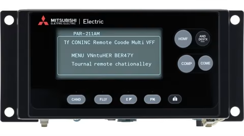
Checking via Wired Remote Control PAR-21MAA
The PAR-21MAA wired remote controller provides a dedicated diagnostic interface for City Multi VRF systems. Follow these steps to retrieve the error code:
Step-by-step guide
- On the PAR-21MAA remote, press the MENU button to open the main menu.
- Navigate to "Maintenance" using the arrow keys and press SELECT.
- Select "Error History" from the maintenance submenu.
- The display will show the most recent error code stored in the system.
- Use the arrow keys to scroll through the error history if multiple codes are stored.
- Note the 4-digit error code displayed.
- Press BACK or CANCEL to exit the menu.
- Enter the 4-digit code in the search field above to find the fault description and solution.
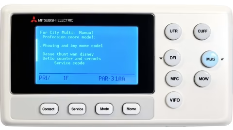
Checking via Wired Remote Control PAR-31MAA
The PAR-31MAA wired remote controller features an enhanced diagnostic interface for City Multi VRF systems. Follow these steps to retrieve the error code:
Step-by-step guide
- On the PAR-31MAA remote, press and hold the FUNCTION button for 3 seconds.
- The display will enter the service mode and show the system status.
- Navigate to "Error Code" using the navigation buttons.
- The current and stored error codes will be displayed on the LCD screen.
- Note the 4-digit error code shown (e.g., 6607, 6831).
- Press the BACK button to exit service mode.
- Enter the 4-digit code in the search field above to find the fault description and solution.